|
Serial I/O Boards
General Standards Corporation is a leading supplier of high speed serial I/O boards for embedded applications on several form factors/busses, and for many operating systems.
Serial protocols include Asynchronous, Bisync, SDLC, HDLC, and IEEE 802.3, synchronous telemetry, simple clock/data ("-SYNC" product line), and di-phase, etc.
Transceiver support RS-422 (V.10), RS-232 (V.28), V.35, RS-530, as well as other software selectable Mixed Protocol modes.
Form factors:
PCI-Express,
PMC,
PC/104-Plus,
PC/104-Express,
VME,
CCPMC,
XMC,
PCI,
PCI-X,
cPCI, and
cPCI-X.
View our large variety of PMC adapters
Software drivers:
Windows,
Linux,
VxWorks,
MathWorks Simulink & xPC Target,
Labview,
QNX, etc.
Free Windows, Linux, and Labview Drivers.
Free loaner boards.
|
Serial I/O Selection Table
Applications include: sonar, battery monitoring, voice digitizing, precision instrumentation, noise monitoring, and sona-buoys, etc.
Read more about Serial IO technology.
View list of products by Form Factor:
PMC,
CCPMC,
XMC,
PCI Products,
PCI Express,
PC/104 Plus,
PC/104 Express,
VME.
For Info on Serial I/O Technology:
[PMC-SIO4BX] - Serial I/O with Software Selectable Cable Tranceivers
Documentation for the Serial Controller (Zilog Z16C30)
Baud Rate Options on Serial I/O Boards
Comparison of the SIO4BX to the SIO4BX-SYNC Boards
Asynchronous serial communication
Comparison of synchronous and asynchronous signalling
Binary Synchronous Communication (Bisync)
High-Level Data Link Control
Synchronous Data Link Control
Biphase mark code (Bi-Phase, di-phase)
RS-422 Transceiver Spec
RS-485 Transceiver Spec
RS-232 Transceiver Spec
EIA-530, RS-530 Cable/Connector Standard
[PMC-SIO4BX]
- Serial I/O with Software Selectable Cable Tranceivers
The PMC-SI04BX board is a four channel serial interface card which
provides high speed, full-duplex, multi-protocol serial capability for PMC
applications. The SIO4BX combines two multi-protocol Dual Universal Serial
Controllers (Zilog Z16C30), 8 FIFOs (up to 256K bytes total), and
multi-protocol transceivers to provide four fully independent asynchronous
or synchronous serial channels. Features include:
Synchronous Serial Data Rates up to 10 Mbits/sec;
Asynchronous Serial Data Rates up to 1 Mbit/sec;
Independent Transmit and Receive FIFOs for each channel - Up to 32 Kbytes
each;
Serial Mode Protocols include Asynchronous, Bisync, SDLC, HDLC, and IEEE
802.3;
Multiprotocol Transceivers support RS422 (V.11)/RS485, RS423 (V.10),
RS232 (V.28), V.35, RS530, as well as other Mixed Protocol modes.
[Back to top for more choices]
[Back to Home for more choices]
Documentation for the Serial Controller (Zilog Z16C30)
The Zilog web site has the specification and User's Manual for the
Z16C30. The User's Manual covers the serial protocols supported by the
Z16C30. To access the Z16C30 User's Manual (.pdf format) just click here.
[http://www.zilog.com/docs/serial/z16c30um.pdf] Here you can view, search,
or print the User's Manual for the Z16C30.
To access the Z16C30 Product Specification (.pdf format) just click here.
http://www.zilog.com/docs/serial/z16c30um.pdf Here you can view, search, or
print the Product Specification for the Z16C30.
Baud Rate Options on Serial I/O Boards
If you cannot achieve the exact baud rate needed for your application
using the factory installed 20MHz clock, you can order the board with a
different oscillator frequency.
The oscillator for the baud rate generator is socketed so we can easily
accommodate any frequency commonly available.
Practically all boards so far have been shipped with the 20MHz oscillator
since the baud rate generator on the Zilog chip provides a lot of
flexibility in baud rate.
We currently do not charge a premium for installing a special frequency,
provided that it is available from stock at a distributor.
Simply add -nn.nMHz to the model number to specify frequency of the
oscillator. For example, for a PMC-SIO4-256K with a 16MHz oscillator for
controlling specify PMC-SIO4-256K-16MHz.
[Back to top for more choices]
[Back to Home for more choices]
Comparison of the SIO4BX to the SIO4BX-SYNC Boards
(applies to all model numbers with '-SYNC)
SIO4BX: The SIO4BX is a high-speed serial card that features the Zilog
Z16C30 serial controller chips. This card is best used when the serial
protocol will be one of the "industry standards" such as HDLC/SDLC,
asynchronous, isochronous, bisync or monosync. The Zilog chips will handle
the protocol specific overhead and add/strip extra information from the
serial data stream to make it match the requested protocol.
This card offers deep FIFO buffers (up to 32KB) to help reduce the risk
of data loss at high clock rates.
The SIO4BX can run up to 10 Mbits/sec in synchronous protocol modes and 1
Mbit/sec in asynchronous mode with the software selectable transceivers set
for differential (RS422/485) mode.
Single-ended modes, such as RS232 and RS423, are limited to 230 kbits/sec.
Drivers are available for Windows, VxWorks and Linux.
SIO4BX-SYNC: The SIO4BX-SYNC is a high-speed synchronous serial card that
basically performs simple serial to parallel conversion of data. It does not
support the high level protocols like the SIO4BX/Zilog chips and does not
add/strip any information to/from the data stream.
This card is best used when the customer is using a proprietary serial
protocol that can be decoded in software or simply needs to send or receive
raw serial data without any of the high level protocol overhead.
This card also offers deep FIFO buffers (up to 256 K byte total) to help
reduce the risk of data loss at high clock rates.
The SIO4BX-SYNC can operate at up to 10 Mbits/sec with the software
selectable transceivers set for differential (RS422/485) mode. Single-ended
modes, such as RS232 and RS423, are limited to 230 kbits/sec. Drivers are
available for Windows, VxWorks and Linux.
[Back to top for more choices]
[Back to Home for more choices]
Asynchronous serial communication
Asynchronous serial communication describes an asynchronous, serial
transmission protocol in which a start signal is sent prior to each byte,
character or code word and a stop signal is sent after each code word. The
start signal serves to prepare the receiving mechanism for the reception and
registration of a character and the stop signal serves to bring the
receiving mechanism to rest in preparation for the reception of the next
character. A common type of start-stop transmission is ASCII over RS-232;
this protocol was developed for use in teletypewriters.
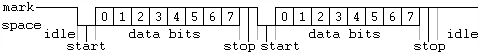
In the diagram, a start bit is sent, followed by eight data bits, no
parity bit and one stop bit, for a 10-bit character frame. The number of
data and formatting bits, and the transmission speed, must be pre-agreed by
the communicating parties.
After the stop bit, the line may remain idle indefinitely, or another
character may immediately be started. [Read more]
[Back to top for more choices]
[Back to Home for more choices]
Comparison of synchronous and asynchronous signalling
Synchronous and asynchronous transmissions are two different methods of
transmission synchronization. Synchronous transmissions are synchronized by
an external clock, while asynchronous transmissions are synchronized by
special signals along the transmission medium.
The need for synchronization
Whenever an electronic device transmits digital (and sometimes analog)
data to another electronic device, there must be a certain rhythm
established between the two devices, i.e., the receiving device must have
some way of knowing, within the context of the fluctuating signal that it's
receiving, where each unit of data begins and where it ends.
For example, a television transmitter produces a continuous stream of
data in which each horizontal line of image must be distinguishable from the
preceding and succeeding lines, so that a TV will be able to distinguish
between them upon reception.
Or, a serial data signal between two PCs must have individual bits and
bytes that the receiving PC can distinguish. If it doesn't, then the
receiving PC can't tell where one byte ends and the next one begins. Or
where one bit ends and begins.
So the signal must be synchronized in a way that the receiver can
distinguish the bits and bytes as the transmitter intends them to be
distinguished.
Methods of synchronization
There are two ways to synchronize the two ends of the communication.
The synchronous signalling methods use 2 different signals. A pulse on
one signal indicates when another bit of information is ready on the other
signal.
The asynchronous signalling methods use only 1 signal. The receiver uses
transitions on that signal to figure out the transmitter bit rate
("autobaud") and timing, and set a local clock to the proper timing,
typically using a phase-locked loop (PLL) to synchronize with the
transmission rate. A pulse from the local clock indicates when another bit
is ready.
Data/strobe Synchronous Transmission
In synchronous transmission, the stream of data to be transferred is
encoded as fluctuating voltages on one wire, and a periodic pulse of voltage
is put on another wire (often called the "clock" or "strobe") that tells the
receiver "here's where one bit/byte ends and the next one begins".
Practically all parallel communications protocols use such synchronous
transmission. For example, in a computer, address information is transmitted
synchronously -- the address bits over the address bus, and the read strobe
in the control bus.
Single Wire Synchronous Transmission
Single-wire synchronous signalingSynchronization can also be embedded
into a signal on a single wire. In differential Manchester encoding, used on
broadcast quality video tape systems[citation needed], each transition from
a low to high or high to low represents a logical zero. A logical one is
indicated when there are two transitions in the same time frame as a zero.
Another example is the Manchester code where a transition from low to high
indicates a one and a transition from high to low indicates a zero. When
there are successive ones or zeros, an opposite transition is required on
the edge of the time frame to prepare for the next transition.
Asynchronous transmission
Main article: Asynchronous communication
In asynchronous transmission, there is only one wire/signal carrying the
transmission. The transmitter sends a stream of data and periodically
inserts a certain signal element into the stream which can be "seen" and
distinguished by the receiver as a sync signal.
[Read more]
[Back to top for more choices]
[Back to Home for more choices]
Binary Synchronous Communication (Bisync)
Binary Synchronous Communication (BSC or Bisync) is an IBM link protocol,
announced in 1967 after the introduction of System/360. It replaced the
synchronous-transmit-receive (STR) protocol used with second generation
computers. The intent was that common link management rules could be used
with three different alphabets for encoding messages. Six-bit Transcode
looked backwards to older systems; USASCII with 128 characters and EBCDIC
with 256 characters looked forward. Transcode disappeared very quickly but
the EBCDIC dialect of Bisync still has very limited use in the 2000s.
Framing
BiSync differs from all popular protocols which succeeded it, in the
complexity of message framing. Later protocols used a single framing scheme
for all messages sent by the protocol. HDLC, Digital Data Communications
Message Protocol (DDCMP), Point-to-Point Protocol (PPP), etc all have
different framing schemes but only one frame format exists within a specific
protocol. Bisync had five different framing formats. Normal data framing
restricted the number of different characters which could be included in a
text block to: Transcode 59, USASCII 123, EBCDIC 251. Transparent data
framing provided an unrestricted alphabet of 64, 128 or 256 characters. The
framing protocol varied with the message content:
Features:
Normal data: restricted character set
Transparent data: unrestricted character set
Single character link control phrase: EOT, NACK etc.
DLE stick: ACK0, ACK1, WACK, RVI, DLE-EOT
Forward abort: STX ... ENQ
Temporary Transmit Delay: (TTD) encoded STX ENQ
All of these frame formats begin with at least two SYNC bytes. The binary
form of the SYNC byte has the property that no rotation of the byte is equal
to the original. This allows the receiver to find the beginning of a frame
by searching the received bit stream for the SYNC pattern. When this is
found, tentative byte synchronization has been achieved. If the next
character is also a SYNC, character synchronization has been achieved. The
receiver then searches for a character which can start a frame. Characters
outside of this set are described as "leading graphics". They are sometimes
used to identify the sender of a frame.
The beginning of a data frame is signalled by the special character SYN
(synchronization). The body of the frame is wrapped between two special
sentinel characters: STX (start of text) and ETX (End of text).
Normal data frames do not allow certain characters to appear in the data.
These are the block ending characters: ETB, ETX and ENQ and the ITB and SYNC
characters. A long data frame should contain an inserted SYNC byte every two
seconds to indicate that character synchronization is still present. The
receiver deletes this character. A normal block ending character (ETB or
ETX) is followed by some kind of checksum. [Read more]
[Back to top for more choices]
[Back to Home for more choices]
High-Level Data Link Control
High-Level Data Link Control (HDLC) is a bit-oriented synchronous data link
layer protocol developed by the International Organization for
Standardization (ISO). The original ISO standards for HDLC were:
ISO 3309 – Frame Structure
ISO 4335 – Elements of Procedure
ISO 6159 – Unbalanced Classes of Procedure
ISO 6256 – Balanced Classes of Procedure
The current standard for HDLC is ISO 13239, which replaces all of those
standards.
HDLC provides both connection-oriented and connectionless service.
HDLC can be used for point to multipoint connections, but is now used
almost exclusively to connect one device to another, using what is known as
Asynchronous Balanced Mode (ABM). The original master-slave modes Normal
Response Mode (NRM) and Asynchronous Response Mode (ARM) are rarely used.
History
HDLC is based on IBM's SDLC protocol, which is the layer 2 protocol for
IBM's Systems Network Architecture (SNA). It was extended and standardized
by the ITU as LAP, while ANSI named their essentially identical version
ADCCP.
Derivatives have since appeared in innumerable standards. It was adopted
into the X.25 protocol stack as LAPB, into the V.42 protocol as LAPM, into
the Frame Relay protocol stack as LAPF and into the ISDN protocol stack as
LAPD. It was the inspiration for the IEEE 802.2 Logical Link Control
protocol, and it is the basis for the framing mechanism used with the
Point-to-Point Protocol on synchronous lines, as used by many servers to
connect to a wide area network, most commonly the Internet. A mildly
different version is also used as the control channel for E-carrier (E1) and
SONET multichannel telephone lines. Some vendors, such as Cisco, implemented
protocols such as Cisco HDLC that used the low-level HDLC framing techniques
but didn't use the standard HDLC header. It has also been used on Tellabs
DXX for destination of Trunk.
Framing
HDLC frames can be transmitted over synchronous or asynchronous links.
Those links have no mechanism to mark the beginning or end of a frame, so
the beginning and end of each frame has to be identified. This is done by
using a frame delimiter, or flag, which is a unique sequence of bits that is
guaranteed not to be seen inside a frame. This sequence is '01111110', or,
in hexadecimal notation, 7E. Each frame begins and ends with a frame
delimiter. A frame delimiter at the end of a frame may also mark the start
of the next frame. A sequence of 7 or more consecutive 1-bits within a frame
will cause the frame to be aborted.
When no frames are being transmitted on a simplex or full-duplex
synchronous link, a frame delimiter is continuously transmitted on the link.
Using the standard NRZI encoding from bits to line levels (0 bit =
transition, 1 bit = no transition), this generates one of two continuous
waveforms, depending on the initial state:
This is used by modems to train and synchronize their clocks via
phase-locked loops. Some protocols allow the 0-bit at the end of a frame
delimiter to be shared with the start of the next frame delimiter, i.e.
'011111101111110'.
For half-duplex or multi-drop communication, where several transmitters
share a line, a receiver on the line will see continuous idling 1-bits in
the inter-frame period when no transmitter is active.
Actual binary data could easily have a sequence of bits that is the same
as the flag sequence. So the data's bit sequence must be modified so that it
doesn't appear to be a frame delimiter.
Synchronous framing
On synchronous links, this is done with bit stuffing. Any time that 5
consecutive 1-bits appear in the transmitted data, the data is paused and a
0-bit is transmitted. This ensures that no more than 5 consecutive 1-bits
will be sent. The receiving device knows this is being done, and after
seeing 5 1-bits in a row, a following 0-bit is stripped out of the received
data. If the following bit is a 1-bit, the receiver has found a flag.
This also (assuming NRZI with transition for 0 encoding of the output)
provides a minimum of one transition per 6 bit times during transmission of
data, and one transition per 7 bit times during transmission of flag, so the
receive can stay in sync with the transmitter. Note however, that for this
purpose encodings such as 8b/10b encoding are better suited.
HDLC transmits bytes of data with the least significant bit first
(little-endian order).
Asynchronous framing
When using asynchronous serial communication such as standard RS-232 serial
ports, bits are sent in groups of 8, and bit-stuffing is inconvenient.
Instead they use "control-octet transparency", also called "byte stuffing"
or "octet stuffing". The frame boundary octet is 01111110, (7E in
hexadecimal notation). A "control escape octet", has the bit sequence
'01111101', (7D hexadecimal). If either of these two octets appears in the
transmitted data, an escape octet is sent, followed by the original data
octet with bit 5 inverted. For example, the data sequence "01111110" (7E
hex) would be transmitted as "01111101 01011110" ("7D 5E" hex). Other
reserved octet values (such as XON or XOFF) can be escaped in the same way
if necessary. [Read more]
Synchronous Data Link Control
Synchronous Data Link Control (SDLC) is a computer communications
protocol. It is the layer 2 protocol for IBM's Systems Network Architecture
(SNA). SDLC supports multipoint links as well as error correction. It also
runs under the assumption that an SNA header is present after the SDLC
header. SDLC was mainly used by IBM mainframe and midrange systems; however
implementations exist on many platforms from many vendors. The use of SDLC
(and SNA) is becoming more and more rare, mostly replaced by IP-based
protocols or being tunneled through IP (using AnyNet or other
technologies).[citation needed]
In 1975, IBM developed the first bit-oriented protocol, SDLC,[citation
needed] from work done for IBM in the early 1970's. This de facto standard
has been adopted by ISO as High-Level Data Link Control (HDLC) in 1979 and
by ANSI as Advanced Data Communication Control Procedures (ADCCP). The
latter standards added features such as the Asynchronous Balanced Mode,
frame sizes that did not need to be multiples of bit-octets, but also
removed some of the procedures and messages (such as the TEST message).
SDLC operates independently on each communications link, and can operate
on point-to-point multipoint or loop facilities, on switched or dedicated,
two-wire or four-wire circuits, and with full-duplex and half-duplex
operation.[4] A unique characterstic of SDLC is its ability to mix
half-duplex secondary stations with full-duplex primary stations on
four-wire circuits, thus reducing the cost of dedicated facilities.[5]
Intel used SDLC as a base protocol for BitBus, still popular in Europe
fieldbus and included support in several controllers (i8044/i8344, i80152).
8044 controller is in production by third party vendors. [Read more]
[Back to top for more choices]
[Back to Home for more choices]
Biphase mark code (Bi-phase, di-phase)
The biphase mark code is a type of encoding for binary data streams. When
a binary data stream is sent without modification via a channel, there can
be long series of logical ones or zeros without any transitions which makes
clock recovery and synchronization difficult. Streams encoded in NRZ are
affected by the same problem. Using biphase mark code makes synchronization
easier by ensuring that there is at least one transition on the channel
between every data bit; in this way it behaves much like the Manchester code
scheme.
When encoding, the symbol rate must be twice the bitrate of the original
signal. Every bit of the original data is represented as two logical states
which, together, form a bit. Every logical 1 in the input is represented as
two different bits (10 or 01) in the output. The input logical 0 is
represented as two equal bits (00 or 11) in the output. Every logical level
at the start of a cell is inversion of the level at the end of the previous
cell. In BMC output the logical 1 and 0 are represented with the same
voltage amplitude but opposite polarities, as shown in the following image:
BMC coding provides a better synchronization since there is a change in
the polarity at least every two bits. It is not necessary to know the
polarity of the sent signal since the information is not kept in the actual
values of the voltage but in their change: in other words it does not matter
whether a logical 1 or 0 is received, but only whether the polarity is the
same or is different from the previous value; this makes synchronization
even easier. Finally, BMC coded signals have zero average DC voltage, thus
reducing the necessary transmitting power and minimizing the amount of
electromagnetic noise produced by the transmission line. All these positive
aspects are achieved at the expense of doubling clock frequency.
It should be noted that BMC is essentially a form of frequency
modulation, where the channel frequency of a data 1 bit is double the
channel frequency of a logical 0 bit.
BMC is used as the encoding method in AES3 and S/PDIF. Many magnetic
stripe cards also use BMC encoding, often called F2F (frequency/double
frequency) or Aiken Biphase. That standard is described in ISO 7811. [Read
more]
[Back to top for more choices]
[Back to Home for more choices]
RS-422 Transceiver Spec
RS-422 is an American national standard ANSI/TIA/EIA-422-B (formerly
RS-422) and its international equivalent ITU-T Recommendation V.11 (also
known as X.27), are technical standards that specify the "electrical
characteristics of the balanced voltage digital interface circuit"[1]. It
provides for data transmission, using balanced or differential signaling,
with unidirectional/non-reversible, terminated or non-terminated
transmission lines, point to point, or multi-drop. In contrast to RS-485
(which is multi-point instead of multi-drop), EIA-422/V.11 does not allow
multiple drivers but only multiple receivers.
The current title of the ANSI standard is TIA-422 Electrical
Characteristics of Balanced Voltage Differential Interface Circuits and is
now in revision B, published in May 1994, and was reaffirmed by the
Telecommunications Industry Association in 2005.
Several key advantages offered by this standard include the differential
receiver, a differential driver and data rates as high as 10 megabaud at 12
metres (40 ft). The specification itself does not set an upper limit on data
rate, but rather shows how signal rate degrades with cable length. The
figure plotting this stops at 10 Mbit/s.
EIA-422 only specifies the electrical signaling characteristics of a
single balanced signal. Protocols and pin assignments are defined in other
specifications. The mechanical connections for this interface are specified
by EIA-530 (DB-25 connector) or EIA-449 (DC-37 connector), however devices
exist which have 4 screw-posts to implement the transmit and receive pair
only. The maximum cable length is 1200 m. Maximum data rates are 10 Mbit/s
at 12 m or 100 kbit/s at 1200 m. EIA-422 cannot implement a truly
multi-point communications network (such as with EIA-485), however one
driver can be connected to up to ten receivers. [Read more]
[Back to top for more choices]
[Back to Home for more choices]
RS-485 Transceiver Spec
EIA-485 (formerly RS-485 or RS485) is an OSI model physical layer
electrical specification of a two-wire,[1] half-duplex, multipoint serial at
1200 m). Since it uses a differential balanced line over twisted pair (like
EIA-422), it can span relatively large distances (up to 4000 feet or just
over 1200 metres).
In contrast to EIA-422, which has a single driver circuit which cannot be
switched off, EIA-485 drivers need to be put in transmit mode explicitly by
asserting a signal to the driver. This allows EIA-485 to implement linear
topologies using only two wires. The equipment located along a set of
EIA-485 wires are interchangeably called nodes, stations and devices.
The recommended arrangement of the wires is as a connected series of
point-to-point (multidropped) nodes, a line or bus, not a star, ring, or
multiply-connected network. Ideally, the two ends of the cable will have a
termination resistor connected across the two wires. Without termination
resistors, reflections of fast driver edges can cause multiple data edges
that can cause data corruption. Termination resistors also reduce electrical
noise sensitivity due to the lower impedance, and bias resistors (see below)
are required. The value of each termination resistor should be equal to the
cable impedance (typically, 120 ohms for twisted pairs). Star and ring
topologies are not recommended because of signal reflections or excessively
low or high termination impedance.
Somewhere along the set of wires, powered resistors are established to
bias each data line/wire when the lines are not being driven by any device.
This way, the lines will be biased to known voltages and nodes will not
interpret the noise from undriven lines as actual data; without biasing
resistors, the data lines float in such a way that electrical noise
sensitivity is greatest when all device stations are silent or unpowered.
Often in a master-slave arrangement when one device dubbed "the master"
initiates all communication activity, the master device itself provides the
bias and not the slave devices. In this configuration, the master device is
typically centrally located along the set of EIA-485 wires, so it would be
two slave devices located at the physical end of the wires that would
provide the termination. The master device would provide termination if it
itself was located at a physical end of the wires, but that is often a bad
design as the master would be better located at a halfway point between the
slave devices. Note that it is not a good idea to apply the bias at multiple
node locations, because, by doing so, the effective bias resistance is
lowered, which could possibly cause a violation of the EIA-485 specification
and cause communications to malfunction. By keeping the biasing with the
master, slave device design is simplified and this situation is avoided.
[Read more]
[Back to top for more choices]
[Back to Home for more choices]
RS-232 Transceiver Spec
In RS-232, user data is sent as a time-series of bits. Both synchronous
and asynchronous transmissions are supported by the standard. In addition to
the data circuits, the standard defines a number of control circuits used to
manage the connection between the DTE and DCE. Each data or control circuit
only operates in one direction, that is, signaling from a DTE to the
attached DCE or the reverse. Since transmit data and receive data are
separate circuits, the interface can operate in a full duplex manner,
supporting concurrent data flow in both directions. The standard does not
define character framing within the data stream, or character encoding.
Voltage levels
Diagrammatic oscilloscope trace of voltage levels for ASCII "K" character
(0x4b) with 1 start bit, 8 data bits, 1 stop bitMain article: Serial port
The RS-232 standard defines the voltage levels that correspond to logical
one and logical zero levels. Valid signals are plus or minus 3 to 15 volts.
The range near zero volts is not a valid RS-232 level; logic one is defined
as a negative voltage, the signal condition is called marking, and has the
functional significance of OFF. Logic zero is positive, the signal condition
is spacing, and has the function ON. The standard specifies a maximum
open-circuit voltage of 25 volts; signal levels of �5 V,�10 V,�12 V, and �15
V are all commonly seen depending on the power supplies available within a
device. RS-232 drivers and receivers must be able to withstand indefinite
short circuit to ground or to any voltage level up to +/-25 volts. The slew
rate, or how fast the signal changes between levels, is also controlled.
Because the voltage levels are higher than logic levels typically used by
integrated circuits, special intervening driver circuits are required to
translate logic levels. These also protect the device's internal circuitry
from short circuits or transients that may appear on the RS-232 interface,
and provide sufficient current to comply with the slew rate requirements for
data transmission.
Because both ends of the RS-232 circuit depend on the ground pin being
zero volts, problems will occur when connecting machinery and computers
where the voltage between the ground pin on one end, and the ground pin on
the other is not zero. This may also cause a hazardous ground loop.
Unused interface signals terminated to ground will have an undefined
logic state. Where it is necessary to permanently set a control signal to a
defined state, it must be connected to a voltage source that asserts the
logic 1 or logic 0 level. Some devices provide test voltages on their
interface connectors for this purpose.
Connectors
RS-232 devices may be classified as Data Terminal Equipment (DTE) or Data
Communications Equipment (DCE); this defines at each device which wires will
be sending and receiving each signal. The standard recommended but did not
make mandatory the D-subminiature 25 pin connector. In general and according
to the standard, terminals and computers have male connectors with DTE pin
functions, and modems have female connectors with DCE pin functions. Other
devices may have any combination of connector gender and pin definitions.
Many terminals were manufactured with female terminals but were sold with a
cable with male connectors at each end; the terminal with its cable
satisfied the recommendations in the standard.
The presence of a 25 pin D-sub connector does not necessarily indicate an
RS-232C compliant interface. For example, on the original IBM PC, a male
D-sub was an RS-232C DTE port (with a non-standard current loop interface on
reserved pins), but the female D-sub connector was used for a parallel
Centronics printer port. Some personal computers put non-standard voltages
or signals on some pins of their serial ports.
The standard specifies 20 different signal connections. Since most
devices use only a few signals, smaller connectors can often be used. For
example, the 9 pin DE-9 connector was used by most IBM-compatible PCs since
the IBM PC AT, and has been standardized as TIA-574. More recently, modular
connectors have been used. Most common are 8P8C connectors. Standard EIA/TIA
561 specifies a pin assignment, but the "Yost Serial Device Wiring Standard"
invented by Dave Yost (and popularized by the Unix System Administration
Handbook) is common on Unix computers and newer devices from Cisco Systems.
Many devices don't use either of these standards. 10P10C connectors can be
found on some devices as well. Digital Equipment Corporation defined their
own DECconnect connection system which was based on the Modified Modular
Jack connector. This is a 6 pin modular jack where the key is offset from
the center position. As with the Yost standard, DECconnect uses a
symmetrical pin layout which enables the direct connection between two DTEs.
Another common connector is the DH10 header connector common on motherboards
and add-in cards which is usually converted via a cable to the more standard
9 pin DE-9 connector (and frequently mounted on a free slot plate or other
part of the housing). [Read More]
[Back to top for more choices]
[Back to Home for more choices]
EIA-530, RS-530 Cable/Connector Standard
EIA-530, or RS-530, is a balanced serial interface standard that
generally uses a 25-pin connector.
The specification defines the cable between the DTE and DCE devices. It
is to be used in conjunction with EIA-422 and EIA-423, which define the
electrical signalling characteristics. Because EIA-530 calls for the more
common 25 pin connector, it displaced the similar EIA-449, which also uses
EIA-422/423, but a larger 37-pin connector.
Two types of EIA-530 are defined: the Category 1, which uses the balanced
characteristics of EIA-422, and Category 2, which is the unbalanced EIA-423.
[Read More]
[Back to top for more choices]
[Back to Home for more choices]
Serial communication
In telecommunication and computer science, serial communication is the
process of sending data one bit at one time, sequentially, over a
communication channel or computer bus. This is in contrast to parallel
communication, where several bits are sent together (on a link comprising of
several wired channels in parallel).
Serial communication is used for all long-haul communication and most
computer networks, where the cost of cable and synchronization difficulties
make parallel communication impractical. At shorter distances, serial
computer buses are becoming more common because of a tipping point where the
disadvantages of parallel busses (clock skew, interconnect density) outweigh
their advantage of simplicity.
[Back to top for more choices]
[Back to Home for more choices]
========= PCIe serial =========
Miscellelanous terms used with PCIe: pcie asynchronous, pcie rs-232, pcie
rs-422, pcie rs-485, pcie serial, pcie serial board, pcie serial card, and
pcie synchronous.
---- PCIe digital ----
Miscellelanous terms used with PCIe:(pcie digital) pcie digital, pcie
digital board, pcie digital card, pcie digital i/o, pcie digital input, pcie
digital io, pcie lvds i/o, and pcie pecl i/o.
---- pcie opto-coupler
Includes: pcie optically isolated, pcie opto, and pcie optoisolated.
========= PMC serial =========
Miscellelanous terms used with PCIe: pmc asynchronous, pmc rs-232, pcie
rs-422, pmc rs-485, pmc serial, pmc serial board, pmc serial card, and pmc
synchronous.
---- PMC digital ----
Miscellelanous terms used with PMC:(pcie digital) pcie digital, pcie
digital board, pcie digital card, pcie digital i/o, pcie digital input, pcie
digital io, pmc lvds i/o, and pmc pecl i/o.
---- PMC opto-coupler
Includes: pmc optically isolated, pmc opto, and pmc optoisolated.
========= PCI serial =========
Miscellelanous terms used with PCI: pci asynchronous, pci rs-232, pci
rs-422, pci rs-485, pci serial, pci serial board, pci serial card, and pci
synchronous.
---- PCI digital ----
Miscellelanous terms used with PCI:(pci digital) pci digital, pci digital
board, pci digital card, pci digital i/o, pci digital input, pci digital io,
pci lvds i/o, and pci pecl i/o.
---- PCI opto-coupler
Includes: pci optically isolated, pci opto, and pci optoisolated.
========= PC/104-Plus serial =========
Miscellelanous terms used with PCIe: 104-plus asynchronous, 104-plus
rs-232, 104-plus rs-422, 104-plus rs-485, 104-plus serial, 104-plus serial
board, 104-plus serial card, and 104-plus synchronous.
---- PC/104-Plus digital ----
Miscellelanous terms used with PC/104-Plus:(104-plus digital) 104-plus
digital, 104-plus digital board, 104-plus digital card, 104-plus digital
i/o, 104-plus digital input, 104-plus digital io, 104-plus lvds i/o, and
104-plus pecl i/o.
---- PC/104-Plus opto-coupler
Includes: 104-plus optically isolated, 104-plus opto, and 104-plus
optoisolated.
========= cPCI serial =========
Miscellelanous terms used with PCIe: cpci asynchronous, cpci rs-232, cpci
rs-422, cpci rs-485, cpci serial, cpci serial board, cpci serial card, and
cpci synchronous.
---- cPCI digital ----
Miscellelanous terms used with cPCI :(cpci digital) cpci digital, cpci
digital board, cpci digital card, cpci digital i/o, cpci digital input, cpci
digital io, pcie lvds i/o, and pcie pecl i/o.
---- cPCI opto-coupler
Includes: cpci optically isolated, cpci opto, and cpci optoisolated.
|
|